
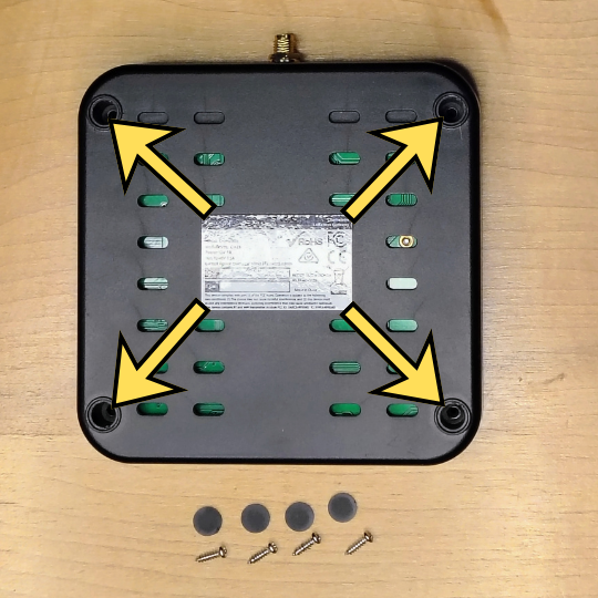
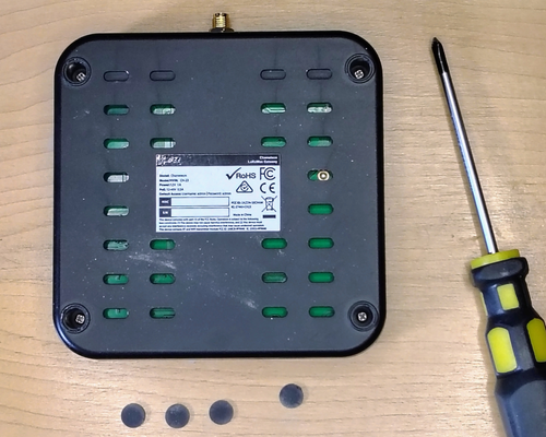
Power off and unplug the SyncroBit and turn it over. Peel off the 4 rubber pads at the corners covering the screw holes, then remove the 4 Phillips screws underneath — those 4 screws hold the case shut.
Tip: Keep the 4 rubber pads and 4 screws together somewhere safe — you'll need them to close the unit back up.
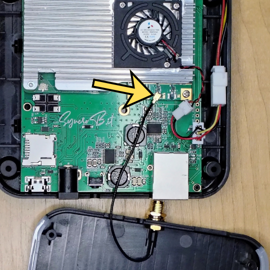
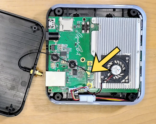
Flip the unit back upright and lift off the top cover. The antenna wire runs from the cover to a small connector on the LoRa board (yellow arrow). Gently pry that connector straight up with a small screwdriver to unplug it — go slow so you don't damage or deform the connector.
The antenna (u.FL) connector is delicate. Pry from directly under the plug, lift evenly, and never tug on the wire itself.
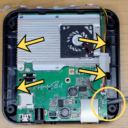
The board is held in place by retaining clips around its edges (arrows). Gently pry up the back edge with a small screwdriver to pop it free of the 4 rear clips, then — keeping the back lifted — slide the board straight back to release the front clips and lift it out of the housing.
Lift evenly and take your time. If the board won't come up, a clip hasn't released yet — never force it.
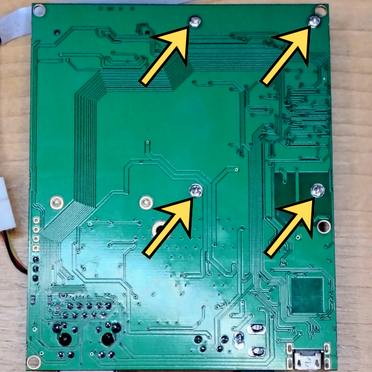
With the board out of the housing, flip it over. On the back, remove the 4 Phillips screws (arrows) that clamp the heatsink down over the Compute Module.
Keep these 4 screws with the others — you'll reuse them to remount the heatsink during reassembly.
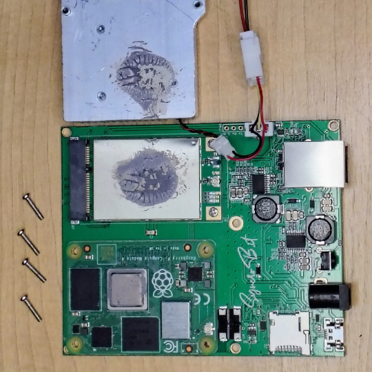
Flip the board back to the front side and lift the heatsink off to reveal the Raspberry Pi Compute Module 4 underneath — the part we'll flash PiLoader OS onto. The old thermal paste can make the heatsink stick, so gently wiggle it while lifting to work it free.
Now's the perfect time to wipe the old thermal paste off both the heatsink and the module, then apply a fresh thin layer at reassembly — it keeps the module running cool.
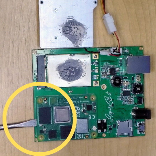
The Compute Module snaps onto the carrier with two board-to-board connectors. Using a small pry bar or flathead screwdriver, gently pry it up from between the two connectors, as shown — this keeps the pressure even across the module and helps avoid damage. Go slowly and gently until it lifts free.
Prying from between the connectors — rather than at a corner or end — lifts both connectors at once and protects their delicate pins. Once free, this module is the part that goes onto the CM4 IO board.
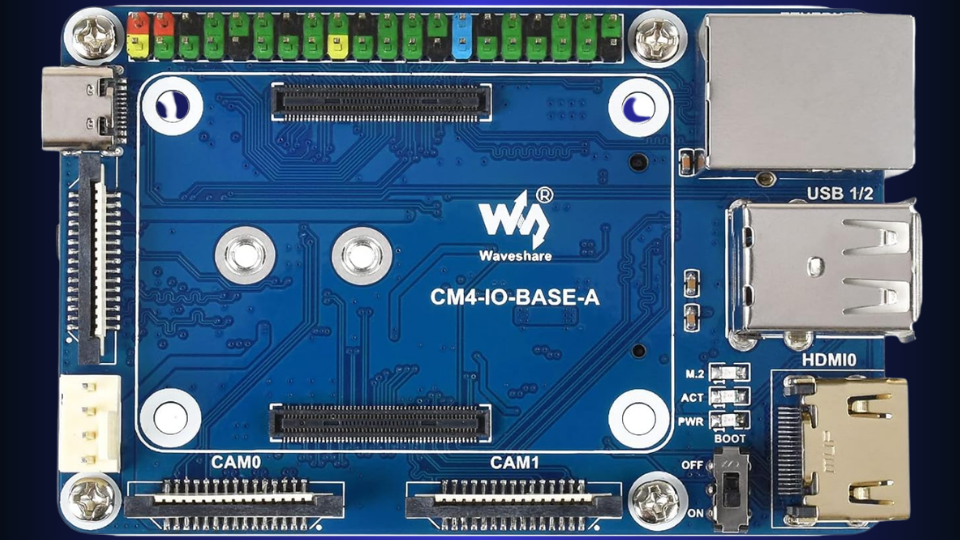
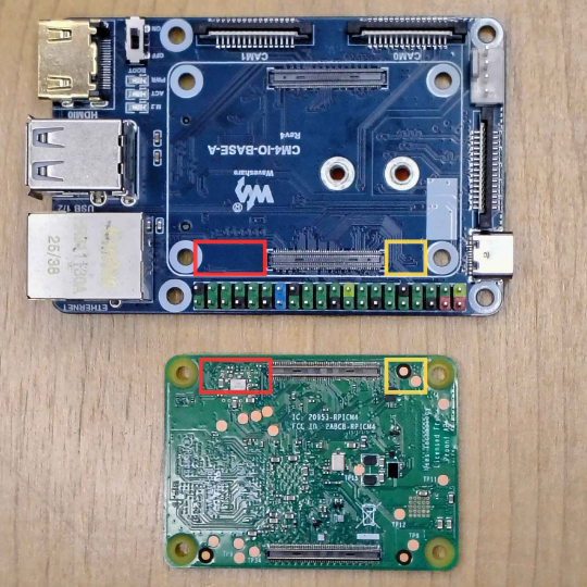
Before pressing the module down, check the orientation against the photo — the red and yellow markers show how the two boards line up. The connectors are offset so the CM4 only fits one way, and the 4 corner holes must match up. Once you're certain the alignment is perfect, press down evenly over both connectors until they snap into place.
If the 4 corner holes don't line up, the connectors aren't aligned — don't press down, or you can bend the connector pins.
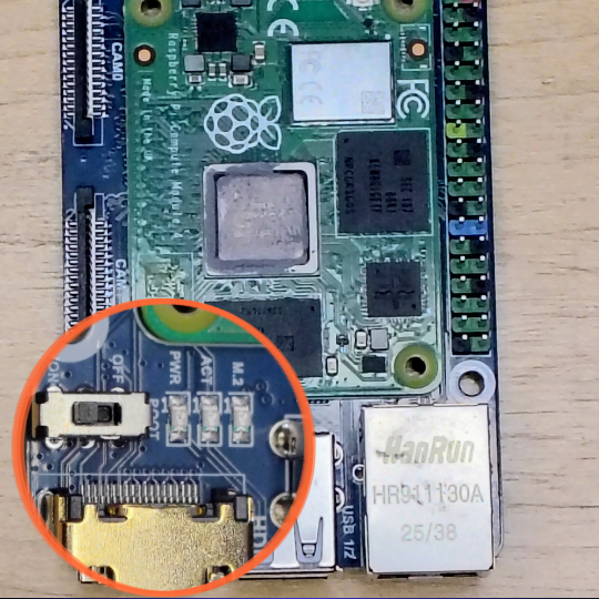
With the module fully seated, slide the IO board's BOOT switch to ON (circled). This overrides the CM4's normal boot priority and puts it into USB flashing mode so your PC can write to it.
If the BOOT switch is left OFF, the module just boots normally and the flasher won't detect it — this is the most common reason a flash won't start.
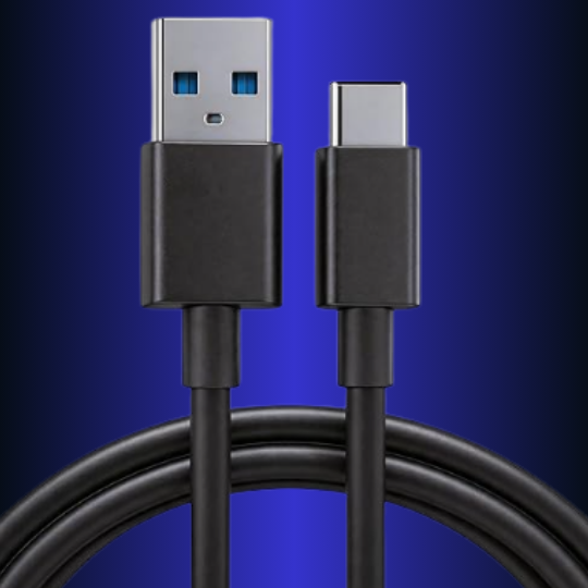
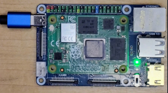
Plug the IO board's USB-C port into your PC with a data cable, and make sure the board is powered. That's the only connection you need for flashing.
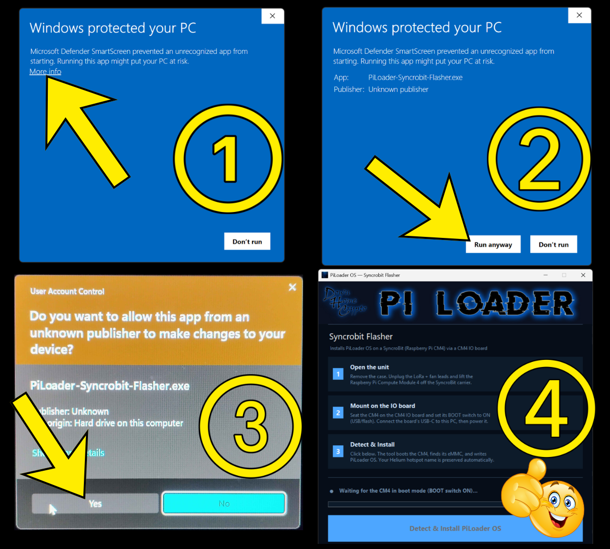
Download the flasher using the button below, then double-click the file to run it. Windows will show a series of warning screens before it opens — this is normal. Work through them in order:
② Same screen expands — click Run anyway
③ User Account Control — click Yes
Because the board is already connected, the flasher should already show a green "CM4 detected in boot mode — ready to install." When it does, click the big Install PiLoader OS button. The tool then writes PiLoader OS and verifies it — about 10–15 minutes. Don't unplug it until it says "Flash Complete ✓."
Not detected? Unplug the USB-C, double-check the CM4 is fully seated on the IO board (both connectors snapped down) and the BOOT switch is ON, then plug it back in — it should detect within a few seconds.
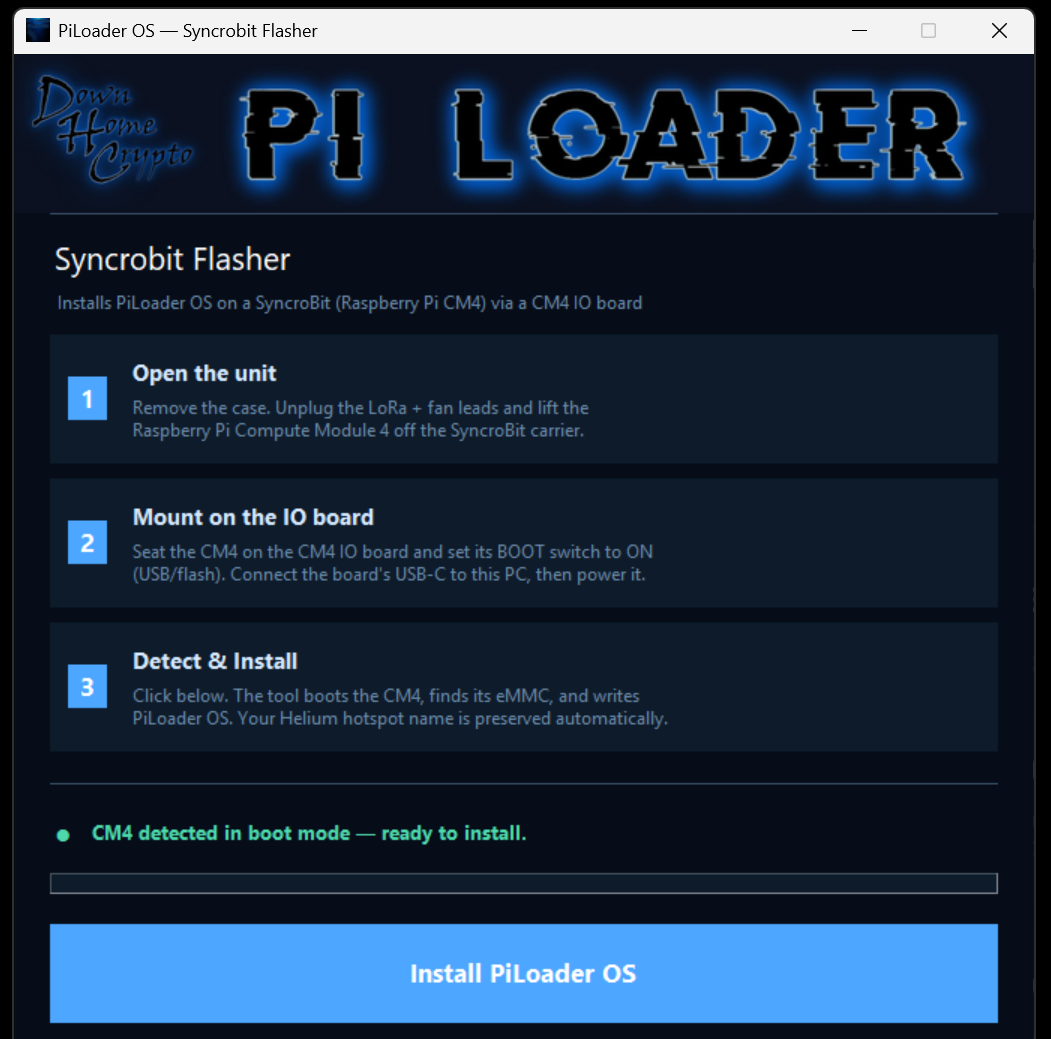
When the write and verify finish, the button turns green and reads "Flash Complete ✓." Your SyncroBit's Compute Module is now running PiLoader OS. It's safe to unplug the IO board.
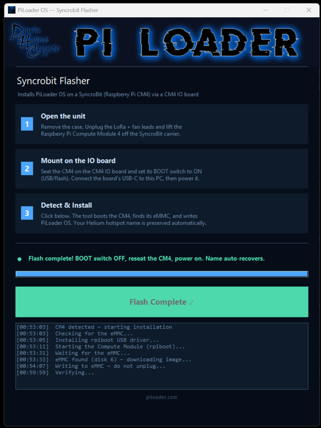
With flashing done, unplug the USB-C cable. Using a small pry bar or flathead screwdriver, gently lift the Compute Module off the CM4 IO board — work slowly and evenly until it pops free of both connectors.
Lift a little at a time and keep the pressure even so you don't bend the connector pins. Never force it.
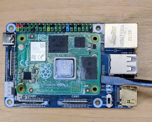
Before reinstalling, make sure all 4 brass spacers are in place on the SyncroBit carrier board (circled). Line the Compute Module up over the two connectors and the corner holes, then apply firm, even pressure until both connectors snap into place.
The connectors are offset so the module only fits one way. If the corner holes don't line up over the spacers, stop and recheck the orientation before pressing down.
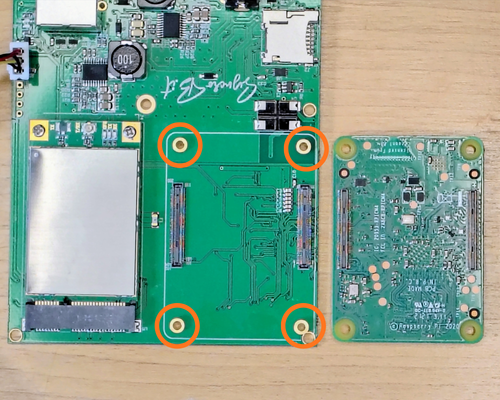
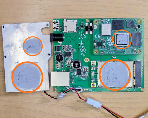
Before attaching the heatsink, this is a great time to refresh the thermal compound. Using isopropyl alcohol, gently clean off the old compound, then apply a light coat to the LoRa card and the CM4 processor — and to their matching spots on the heatsink (circled).
A thin, even layer is all you need — too much actually traps heat. Fresh compound keeps the module and LoRa card running cool.
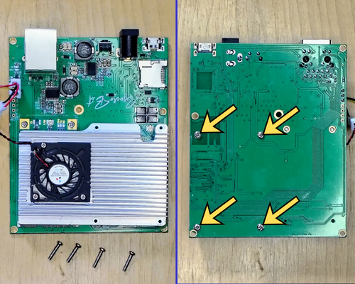
Align the heatsink over the CM4, paying special attention to lining up the screw holes. Then flip the board face down and install the 4 machine screws (arrows) to mount the heatsink to the board.
Tip: Start all 4 screws a few turns first, then tighten them down — that keeps the heatsink aligned and the holes from drifting.
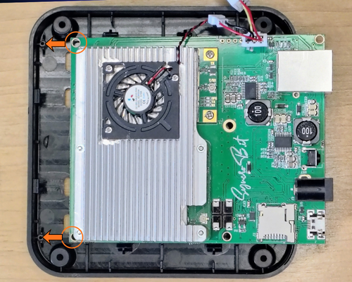
Slide the holes on the front edge of the board over the plastic mounting posts in the bottom half of the case (arrows), then press the board down to snap it into place.
Hook the front edge onto the posts first, then lower the back — the rear retaining clips will click as the board seats flat.
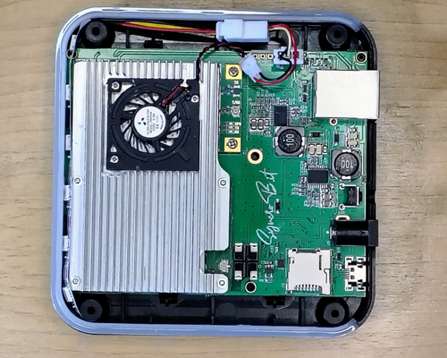
Route the LED light strip around the outside of the mounting posts, then seat the LED lens in place.
Keep the LED strip on the outside of the posts so it doesn't get pinched when the cover goes back on.
Gently reattach the antenna wire to the LoRa card (arrow). Line the connector up directly over its terminal, then push down gently until it snaps into place.
The u.FL connector is delicate — make sure it's centered over the terminal before pressing, and push straight down so you don't bend it.
Install the top cover, then flip the miner over and install the 4 cover retaining screws. Finally, cover the screw holes with the 4 rubber foot pads — the same ones you set aside in step 01.
That's the hardware done — your SyncroBit is fully reassembled and ready to power back on.
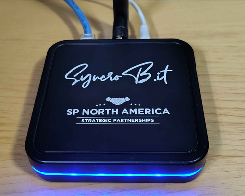
Connect the antenna, network cable, and power to boot up the miner. PiLoader OS boots automatically — wait about 60–90 seconds for the full boot and the blue LED ring to light up.
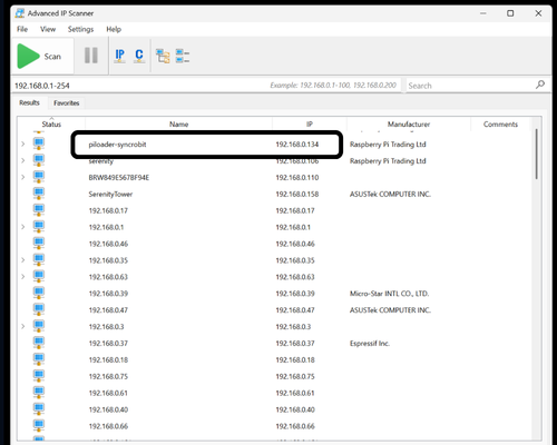
Open Advanced IP Scanner on your PC and click Scan. Look for a device named piloader-syncrobit in the results list — the IP address next to it is what you need.
Alternatively, log into your home router (usually at 192.168.0.1 or 192.168.1.1) and check its connected-devices list.
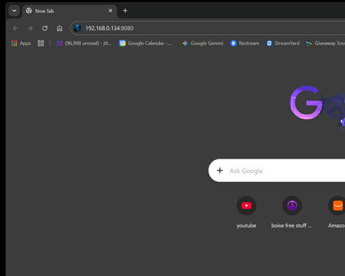
On any device connected to your home network, open a browser and type your device's IP address followed by :8080. For example: 192.168.0.134:8080.
You should see the PiLoader OS setup screen. Bookmark this address for easy access going forward.
Shortcut — only one PiLoader device?
Use piloader.local:8080 instead of the IP. With a license you can also set a custom name (e.g. garage.local) — handy for multi-device setups.
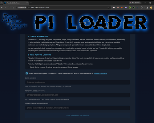
Read through the Terms and Conditions and accept them. Enter your email address — this is required for password recovery and license registration, so make sure it's accurate. Choose a strong, unique password for your dashboard, then click "Save Password & Continue" to proceed.
Save 10%: Enter referral code SERENITY in the optional Referral Code field to take 10% off your license price.
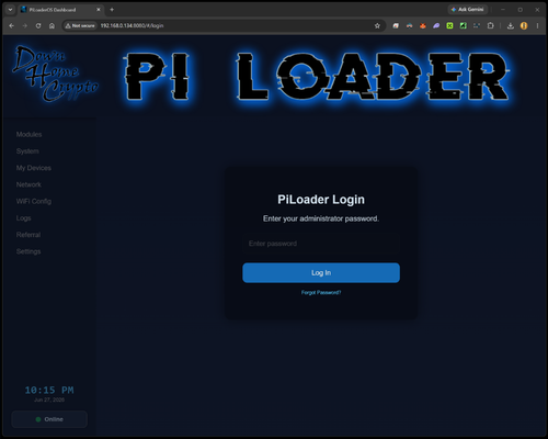
Enter the password you just set and click "Log In".
Welcome to your PiLoader OS dashboard — this is your command center. From here you can install and manage your earning modules, monitor your hardware health, configure your network and WiFi settings, set your local time zone, and access everything PiLoader has to offer.
You did the hard work — now let your miner start earning for you.
You're Live!
Your SyncroBit is now running PiLoader OS, and your Helium hotspot name has recovered automatically. Head to the Modules section and start enabling your earning apps. Good luck out there — and Happy Mining! 🎉
Join the PiLoader Discord community for the latest news, help from fellow PiLoader miners, and to share your mining adventure with people who get it.